Home › Unlabelled ›
Opto Isolated Relay Schematic - Digital I O Basic Knowledge Contec : The opto inputs provide a link selectable internal isolated + 5v , 0v or external + 5v , 0v opto supply
Opto Isolated Relay Schematic - Digital I O Basic Knowledge Contec : The opto inputs provide a link selectable internal isolated + 5v , 0v or external + 5v , 0v opto supply. The opto isolator isolates 2 circuits electronically by sending data as light. Overkill for sure, but the design provides for that. In fact we can even change the polarity of the higher voltage supplies without regard to the digital circuit common negative grounds if needed. I am controlling a relay with stm32 micro controller. Low level trigger expansion board, which is.
I am controlling a relay with stm32 micro controller. Standard interface that can be controlled directly by microcontroller (arduino , 8051, avr. The pins are counted up from that pin until reaching the other side of the cable. This solution provides secure switching with optical (light) signal, increasing the power characteristics of. 10a 250v ac 10a 30v dc although this would be less for inductive loads.
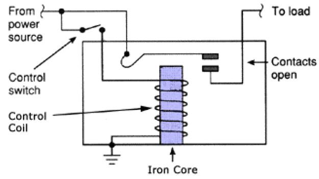
Opto Isolated Relay Switching Module Arduino And Raspberry Pi Compatible from www.zen22142.zen.co.uk In fact we can even change the polarity of the higher voltage supplies without regard to the digital circuit common negative grounds if needed. Fritzing/jtron 1 channel optoisolated relay module.fzpz. I am controlling a relay with stm32 micro controller. A wide variety of opto isolated relay options are available to you, such as theory, usage, and contact load. It has 2 separate vcc and 2 separate ground connections. Alibaba.com offers 521 opto isolated relay products. 12v power supply required for the board. The working of a relay can be better understood by explaining the following diagram given below.
With idc cables, the red pin generally denotes pin 1.
The module has two spdt relays which can switch: Relays are frequently used in our electronics applications specially when we need to drive high loads from microcontroller circuits. This solution provides secure switching with optical (light) signal, increasing the power characteristics of. I am controlling a relay with stm32 micro controller. Low level trigger expansion board, which is. 12v relay interface with fan 340 opto isolator fan of etri lm35 interfacing lm35 application of automatic fan controller using lm35 sensor in future pc hard disk circuit diagram wd text: A wide variety of opto isolated relay options are available to you, such as theory, usage, and contact load. 4 channel 5v optical isolated relay module. To allow a simple microcontroller for anyone else considering this for isolated interfacing to serial comms of not yet determined levels. The outputs are software configurable as sourcing or sinking. The gate input is optically isolated and the mosfets drain pins connect to the ac load. To keep pace with advances in the. It has 2 separate vcc and 2 separate ground connections.
4 channel 5v optical isolated relay module. The examples so far have considered only arrangements that connect a single isolated module to a normal bus. Overkill for sure, but the design provides for that. Standard interface that can be controlled directly by microcontroller (arduino , 8051, avr. To keep pace with advances in the.
Arduino Lesson 2 Channel Relay Module Osoyoo Com from osoyoo.com The pins are counted up from that pin until reaching the other side of the cable. The module has two spdt relays which can switch: A wide variety of opto isolated relay options are available to you, such as theory, usage, and contact load. To allow a simple microcontroller for anyone else considering this for isolated interfacing to serial comms of not yet determined levels. With idc cables, the red pin generally denotes pin 1. The examples so far have considered only arrangements that connect a single isolated module to a normal bus. To keep pace with advances in the. In fact we can even change the polarity of the higher voltage supplies without regard to the digital circuit common negative grounds if needed.
This is a 8 channel relay interface board using uln2803.
To keep pace with advances in the. The opto isolator isolates 2 circuits electronically by sending data as light. This solution provides secure switching with optical (light) signal, increasing the power characteristics of. Low level trigger expansion board, which is. With idc cables, the red pin generally denotes pin 1. 12v power supply required for the board. A wide variety of opto isolated relay options are available to you, such as theory, usage, and contact load. The examples so far have considered only arrangements that connect a single isolated module to a normal bus. Fritzing/jtron 1 channel optoisolated relay module.fzpz. The working of a relay can be better understood by explaining the following diagram given below. This is a 8 channel relay interface board using uln2803. Overkill for sure, but the design provides for that. Aerotech soloist cp manual online:
The spice model is available for this device (but has not gone into easyeda yet). Alibaba.com offers 521 opto isolated relay products. Posted on 04.02.2020 by admin. 12v relay interface with fan 340 opto isolator fan of etri lm35 interfacing lm35 application of automatic fan controller using lm35 sensor in future pc hard disk circuit diagram wd text: The opto inputs provide a link selectable internal isolated + 5v , 0v or external + 5v , 0v opto supply
What Is The Purpose Of The Optocoupler In This Circuit To Drive The Mosfet Relay Electrical Engineering Stack Exchange from i.stack.imgur.com 12v power supply required for the board. A wide variety of opto isolated relay options are available to you, such as theory, usage, and contact load. Posted on 04.02.2020 by admin. Alibaba.com offers 521 opto isolated relay products. The opto isolator isolates 2 circuits electronically by sending data as light. The gate input is optically isolated and the mosfets drain pins connect to the ac load. To allow a simple microcontroller for anyone else considering this for isolated interfacing to serial comms of not yet determined levels. Here we designed an isolated pcb for 4 relays so we can operate 4 ac appliances at a time.
I am controlling a relay with stm32 micro controller.
This is a 8 channel relay interface board using uln2803. The opto inputs provide a link selectable internal isolated + 5v , 0v or external + 5v , 0v opto supply I am controlling a relay with stm32 micro controller. 4 channel 5v optical isolated relay module. The outputs are software configurable as sourcing or sinking. This solution provides secure switching with optical (light) signal, increasing the power characteristics of. For lower frequency precision isolated dc amplification? The spice model is available for this device (but has not gone into easyeda yet). To keep pace with advances in the. With idc cables, the red pin generally denotes pin 1. Relays are frequently used in our electronics applications specially when we need to drive high loads from microcontroller circuits. The working of a relay can be better understood by explaining the following diagram given below. It has 2 separate vcc and 2 separate ground connections.
Standard interface that can be controlled directly by microcontroller (arduino , 8051, avr opto isolated relay. The opto isolator isolates 2 circuits electronically by sending data as light.