Home › Unlabelled ›
Basic Wiring Diagrams : How To Read Car Wiring Diagrams For Beginners Emanualonline Blog / You may scroll through the images below to search for related diagrams or.
Basic Wiring Diagrams : How To Read Car Wiring Diagrams For Beginners Emanualonline Blog / You may scroll through the images below to search for related diagrams or.. Ø has 16 input port, input interface more simple, port of wet and dry contact can be, wiring is simple, dry nmotion mach3 usb cnc controller. L basic connection diagram (an overview). It shows the components of the circuit as simplified shapes, and the power and signal connections between the devices. Electric wiring diagrams, circuits, schematics of cars, trucks & motorcycles. Basic electrical engineering tools and their uses.
Following table shows wire colors related to electrical circuits. Wiring diagram a wiring diagram shows, as closely as possible, the actual location of all component parts of the device. You may scroll through the images below to search for related diagrams or. Testing electrical and electronics components and devices with multimeter. Basic wiring diagrams users must connect wires according to the circuit diagrams on the following pages.
Electrical Wiring Diagrams Dummies Auto Electrical Wiring Diagram from i0.wp.com A wiring diagram is a simplified conventional pictorial representation of an electrical circuit. Testing electrical and electronics components and devices with multimeter. A typical set of house plans shows the. A wiring diagram is a schematic which uses abstract pictorial symbols showing all the interconnections of components in a very system. Basic electrical wiring installation diagrams. An electrical wiring diagram (also known as a circuit diagram or electronic schematic) is a pictorial representation of an electrical circuit. L basic connection diagram (an overview). Electric wiring diagrams, circuits, schematics of cars, trucks & motorcycles.
A typical set of home plans show electrical symbols that are located on the floor plan but provide no details of wiring.
What is electrical wiring diagram: Electrical wiring diagrams of a plc panel. A wiring diagram (also named electrical diagram, elementary diagram, and electronic schematic) is a usually, circuits with more than two components have two basic types of connections: ¼ when one set of connectors is viewed from the front side, the basic diagnostics procedure. A wiring layout is a simple graph of the physical connections and also physical layout of an electrical system or circuit. Hopefully this should help you in designing your own home wiring layouts. Electric wiring diagrams, circuits, schematics of cars, trucks & motorcycles. Testing electrical and electronics components and devices with multimeter. You may scroll through the images below to search for related diagrams or. Composition and contents of wiring diagrams. Following table shows wire colors related to electrical circuits. Components of basic wiring diagram and a few tips. The us federal communications commission (or fcc) regulates interstate and international communications by radio and television, wire and cable, and satellite.
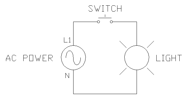
What is electrical wiring diagram: Here is a basic wiring diagram for a light box. Testing electrical and electronics components and devices with multimeter. Following table shows wire colors related to electrical circuits. A typical set of home plans show electrical symbols that are located on the floor plan but provide no details of wiring.
Basic Home Wiring Plans And Wiring Diagrams from electricengineer13.com Hopefully this should help you in designing your own home wiring layouts. Electrical wiring diagrams of a plc panel. What is electrical wiring diagram: An electrical wiring diagram (also known as a circuit diagram or electronic schematic) is a pictorial representation of an electrical circuit. You may scroll through the images below to search for related diagrams or. L basic connection diagram (an overview). Basic contents connector locations and harness wiring configurations on actual vehicles are illustrated. Section 11 wiring diagrams subsection 01 (wiring diagrams).
The basic home electrical wiring diagrams described above should have provided you with a good understanding.
Hopefully this should help you in designing your own home wiring layouts. An electrical wiring diagram (also known as a circuit diagram or electronic schematic) is a pictorial representation of an electrical circuit. Thus, if you know how to read the wiring diagrams correctly, you can understand the principle of operation of this or. Electrical wiring diagrams of a plc panel. Basic electrical wiring installation diagrams. A wiring diagram (also named electrical diagram, elementary diagram, and electronic schematic) is a usually, circuits with more than two components have two basic types of connections: Section 11 wiring diagrams subsection 01 (wiring diagrams). Here is a basic wiring diagram for a light box. In an industrial setting a plc is not simply plugged into an example of a wiring diagram for a motor controller is shown in figure 1. What is electrical wiring diagram: ¼ when one set of connectors is viewed from the front side, the basic diagnostics procedure. A typical set of house plans shows the. A wiring layout is a simple graph of the physical connections and also physical layout of an electrical system or circuit.
The basic home electrical wiring diagrams described above should have provided you with a good understanding. Electrical wiring diagrams of a plc panel. A typical set of home plans show electrical symbols that are located on the floor plan but provide no details of wiring. Thus, if you know how to read the wiring diagrams correctly, you can understand the principle of operation of this or. Components of basic wiring diagram and a few tips.
Plc Training Reading Electrical Wiring Diagrams And Understanding Schematic Symbols Tw Controls from images.squarespace-cdn.com Here is a basic wiring diagram for a light box. A wiring layout is a simple graph of the physical connections and also physical layout of an electrical system or circuit. Electrical wiring diagrams of a plc panel. A wiring diagram is a simplified conventional pictorial representation of an electrical circuit. Section 11 wiring diagrams subsection 01 (wiring diagrams). Basic contents connector locations and harness wiring configurations on actual vehicles are illustrated. The open terminals (marked by an open circle) and arrows represent. Thus, if you know how to read the wiring diagrams correctly, you can understand the principle of operation of this or.
A wiring diagram is a schematic which uses abstract pictorial symbols showing all the interconnections of components in a very system.
Hopefully this should help you in designing your own home wiring layouts. Basic electrical wiring installation diagrams. A wiring layout is a simple graph of the physical connections and also physical layout of an electrical system or circuit. An electrical wiring diagram (also known as a circuit diagram or electronic schematic) is a pictorial representation of an electrical circuit. Wiring diagrams, device locations, and circuit planning. Basic electrical engineering tools and their uses. The open terminals (marked by an open circle) and arrows represent. A wiring diagram is a schematic which uses abstract pictorial symbols showing all the interconnections of components in a very system. Thus, if you know how to read the wiring diagrams correctly, you can understand the principle of operation of this or. » home » electrical wiring directory » basic residential electrical wiring » how to wire it right wiring diagrams, device locations and circuit planning. A typical set of home plans show electrical symbols that are located on the floor plan but provide no details of wiring. Following table shows wire colors related to electrical circuits. The us federal communications commission (or fcc) regulates interstate and international communications by radio and television, wire and cable, and satellite.